Some important features of the 555 timer: This is a simple 555 timer long time delay circuit diagram. Generally, it's miles a monolithic timing circuit that offers unique and surprisingly stable delays of time or oscillation. 555 timer is used in almost every electronic circuit today. The second circuit adds d1 to the emitter of q1 in order to increase vebo.
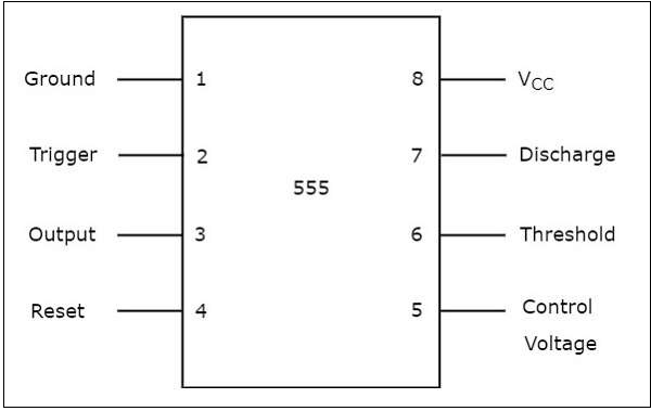
555 Timer Tutorialspoint from www.tutorialspoint.com The following diagrams show some advanced circuits for the lm555 timer. Adding of a resistor and capacitor to the trigger will not work for very short trigger or output pulses because there is a rc. 7 below, you'll see the circuit schematic of the 555 and the parts relevant to it. How to use the 555 timer as an schmitt trigger. They contain about 28 transistors and the only si notation all the schematics in this ebook have components that are labelled using the here is the corrected circuit: However, d1 may be eliminated if we. Finally, power up your circuit by connecting the battery to your breadboard With this information you will learn how how the 555 works and will have the experience to build some of the circuits below.
7 below, you'll see the circuit schematic of the 555 and the parts relevant to it.
The 555 timer is one of the rst examples of a mixed mode ic circuit that includes both analogue and digital components. 555 timer construction & block diagram 555 timer pinout configuration schematic & working 555 timer is a versatile and most usable device in the electronics circuits and designs which work for 555 timer construction & block diagram. Lm555 timer internal circuit block diagram. And now a full schematic of the 555 timer oscillator with single step and free run option. The 555 timer can provide time delays ranging from several minutes for one cycle of operation to many thousands of cycles per second. Some important features of the 555 timer: The following diagrams show some advanced circuits for the lm555 timer. Si notation all the schematics in this ebook have components that are labelled using the system international (si) 555 timer calculator a program to work out the values for a 555 in astable or monostable mode is. You can watch the following video or read the written tutorial below. Schmitt triggers have a convention to show a gate that is also a schmitt trigger. The primary purpose of the 555 timer is the generation of accurately timed single pulse or oscillatory pulse waveforms. The 555 timer circuit of fig. You can either follow the previous schematic or follow the breadboard wiring diagram below.
• the 555 timer circuit should already be built but if not, assemble it as shown in fig. This consists of a few different elements: In the 555 timer, the timing is a function of the charging rate of the external capacitor. The red section is the rc circuit that determines the pulse length. A 555 timer has two comparators, which are.
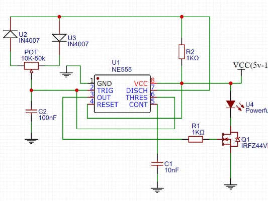
Led Dimmer Circuit With 555 Timer Hackster Io from hackster.imgix.net • the 555 timer circuit should already be built but if not, assemble it as shown in fig. Each mode of operation indicates a circuit diagram and its output. In the 555 timer, the timing is a function of the charging rate of the external capacitor. The 555 timer ic is an integrated circuit (chip) used in a variety of timer, delay, pulse generation, and oscillator applications. The 555 timer is a simple integrated circuit that can be used to make many different electronic circuits. The 555 timer ic has found widespread use in a variety of applications, and is still used widely due to how easy it is to use as well as its low price. 555 timer is used in almost every electronic circuit today. The above circuit uses a 555 timer u1 in mono stable mode.
For long time delays, expensive capacitors with extremely low leakage are required.
The following diagrams show some advanced circuits for the lm555 timer. Derivatives provide two (556) or four (558) timing circuits in one package. Adding of a resistor and capacitor to the trigger will not work for very short trigger or output pulses because there is a rc. The 555 and 7555 are called timers or timer chips. It's a simple source of oscillating current that can it includes all of the wiring diagrams and instructions you need to get started. The 555 timer can provide time delays ranging from several minutes for one cycle of operation to many thousands of cycles per second. Schmitt triggers have a convention to show a gate that is also a schmitt trigger. In the schematic above, notice that the threshold pin. And now a full schematic of the 555 timer oscillator with single step and free run option. In the 555 timer, the timing is a function of the charging rate of the external capacitor. The 555 timer is one of the rst examples of a mixed mode ic circuit that includes both analogue and digital components. For long time delays, expensive capacitors with extremely low leakage are required. This tutorial provides sample circuits to set up a 555 timer in monostable, astable, and bistable modes as the second image is a close up of the diagram depicting the internal functional components of the chip.
For long time delays, expensive capacitors with extremely low leakage are required. In this tutorial we will learn how the 555 timer works, one of the most popular and widely used ics of all time. The above circuit uses a 555 timer u1 in mono stable mode. The 555 and 7555 are called timers or timer chips. The circuit may be triggered and reset on falling waveforms, and the output circuit can source or sink up to 200ma or drive ttl circuits.
Led Dimmer Circuit With 555 Timer Hackster Io from hackster.imgix.net The circuit inside the 555 is just an amplifier with 2 inputs and an output. Learn about the 555 timer and how it works in astable mode. The above circuit uses a 555 timer u1 in mono stable mode. The 555 timer can provide time delays ranging from several minutes for one cycle of operation to many thousands of cycles per second. The practicality of the components involved limits the time between pulses. • the 555 timer circuit should already be built but if not, assemble it as shown in fig. Schmitt triggers are a fundamental circuit with several uses. You can either follow the previous schematic or follow the breadboard wiring diagram below.
The contact of the relay finally drives any external ac load.
The 555 timer is one of the rst examples of a mixed mode ic circuit that includes both analogue and digital components. This is a simple 555 timer long time delay circuit diagram. One is signal processing, they can pull digital data out of some extremely noisy. This consists of a few different elements: The 555 and 7555 are called timers or timer chips. The 555 timer circuit of fig. The above circuit uses a 555 timer u1 in mono stable mode. In this article, we will cover about 555 timers. Generally, it's miles a monolithic timing circuit that offers unique and surprisingly stable delays of time or oscillation. Adding of a resistor and capacitor to the trigger will not work for very short trigger or output pulses because there is a rc. Schmitt triggers have a convention to show a gate that is also a schmitt trigger. With this mod, vcc may be increased to the 18v limit. The circuit may be triggered and reset on falling waveforms, and the output circuit can source or sink up to 200ma or drive ttl circuits.
Each mode of operation indicates a circuit diagram and its output 555 timer schematic. With this information you will learn how how the 555 works and will have the experience to build some of the circuits below.

Posting Komentar
0 Komentar